Working with servos and an Arduino Nano clone

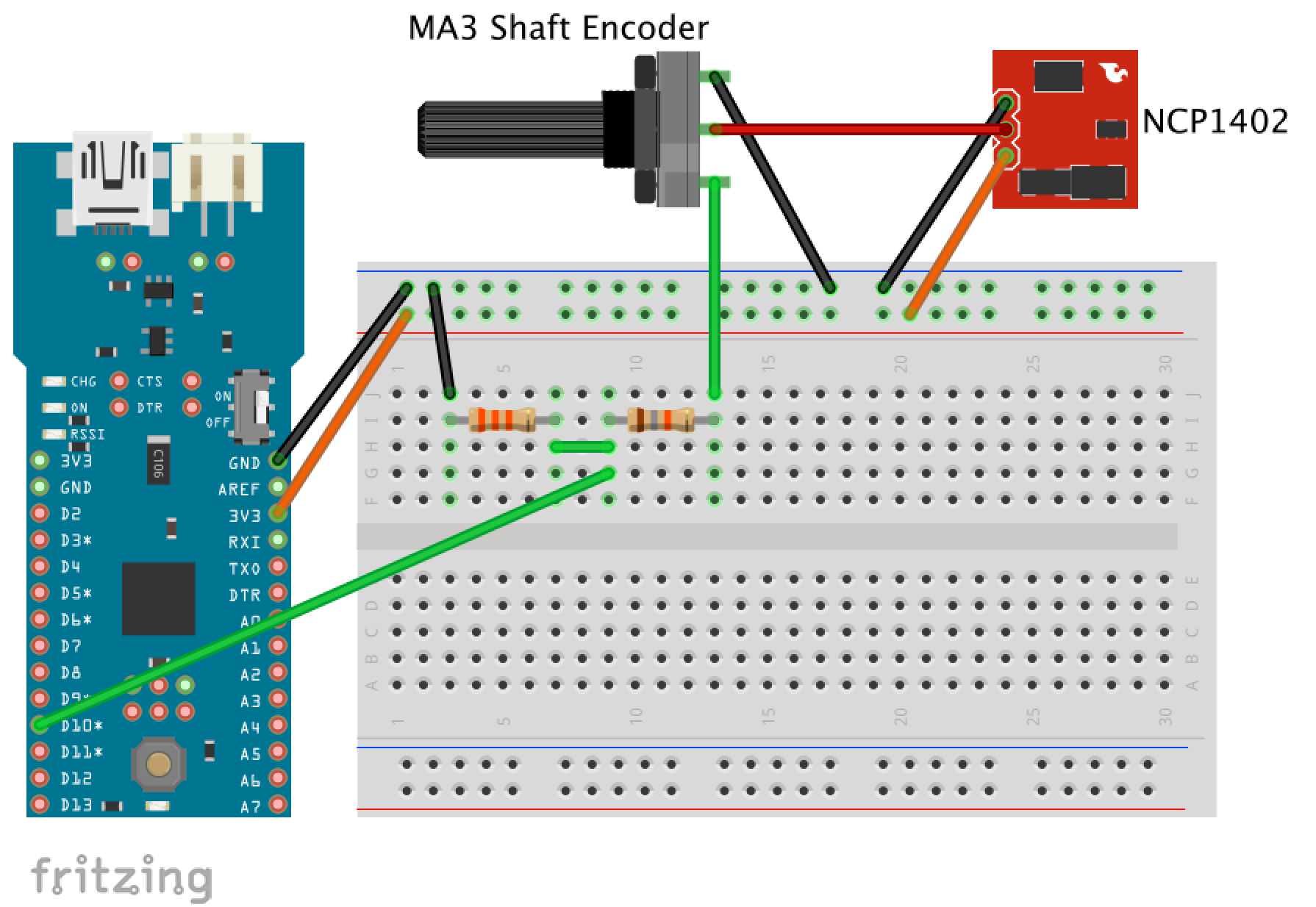
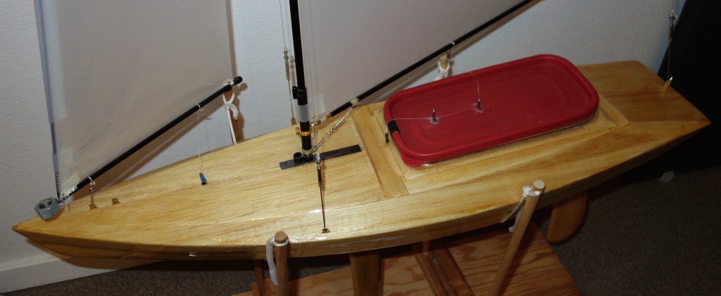
Over the past few weeks I have been working on building the software to allow my RC Sailboat to sail autonomously. To keep the form factor as small and light as possible, I bought a cheap Arduino Nano clone to use in place of an Arduino Uno.

Nano with rudder and Sail
Nano microcontroller with servos for sail and rudder control

Obstacle 1: drivers

My first obstacle was getting my mac to communicate with the board. The basic issue is that the WCH340G USB interface chip on the clone is different than the FTDI FT232RL used on the authentic Arduino Nano. There are many sites with instructions and links to drivers, but this one had the most up to date driver that was signed. The older drivers were not signed and required me to bypass OSX’s security to allow unsigned drivers. direct link to driver download

Obstacle 2: consistent power

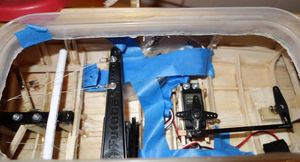
I had some semi-working software running on the Uno that would adjust a sail and rudder servo. When I swapped in the Nano the servos generally worked, but would sometimes move wildly or jitter. Since the Nano and Uno are very similar (chip, ram, clock speed, etc.) I figured the issue was going to be with the power or maybe the WCH340G USB chip.

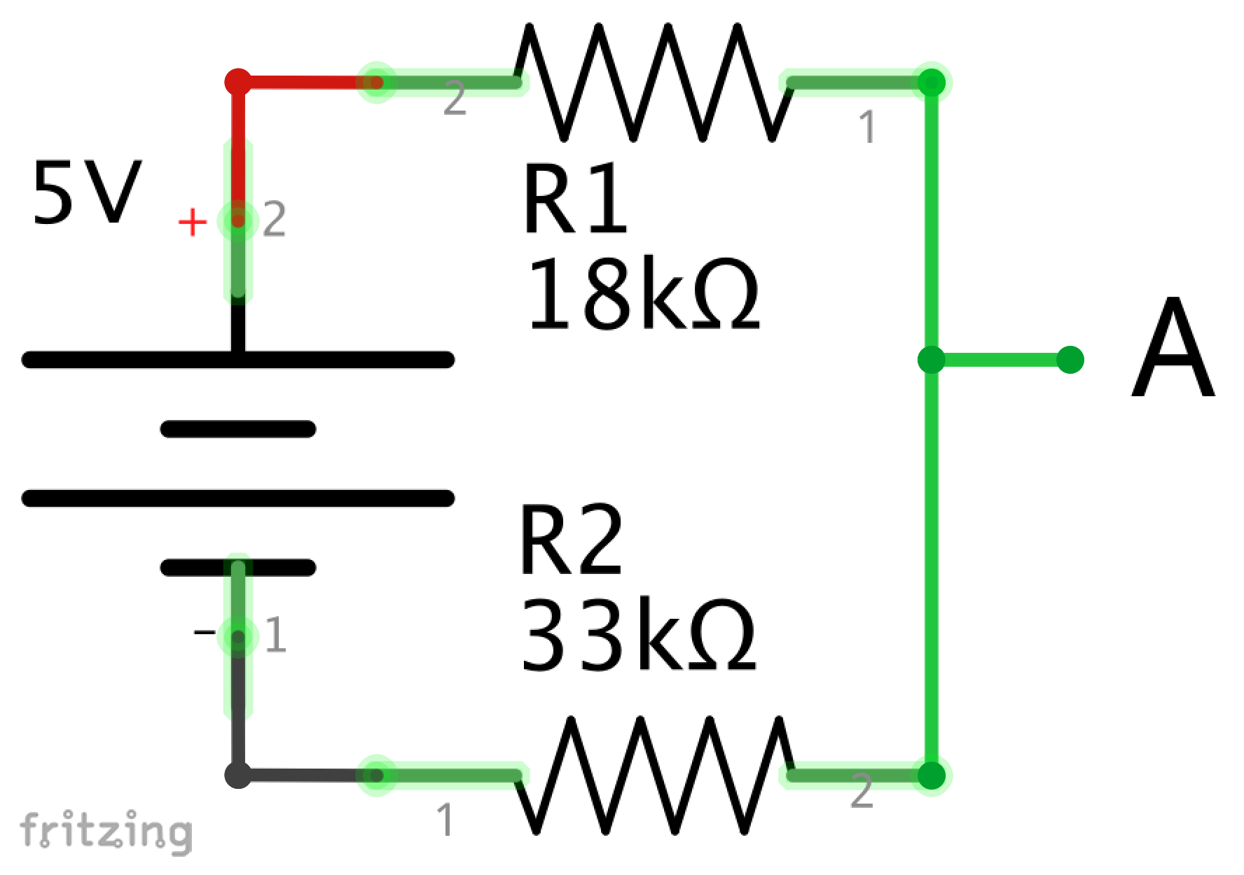
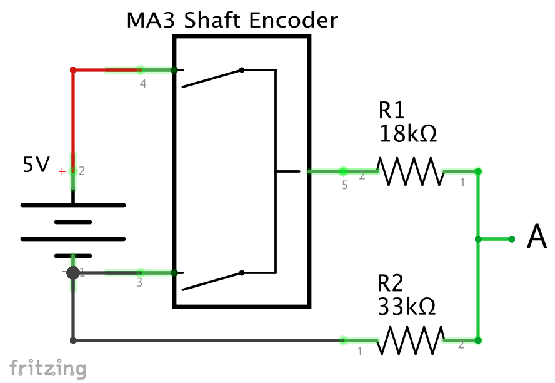
To troubleshoot, I used my voltmeter to see how the Nano voltage changed while adjusting the servos. When not moving the servos, it put out 4.8V on the 5V pin and while moving the servos simultaneously it would drop to ~4.2V. The servos expect 4.8-6V so this could contribute to the issue. As reference, the Uno put out 5V, I didn’t test it while moving servos.

In the past I have had issues with macs not putting out enough voltage through USB, and I have a cord that includes 2 plugs, one for power and one for power+data. The cord is similar to this one.

I swapped out the cords and the servos started behaving as expected. My guess is that a combination of data transfers (to signal the servo change) and keeping a consistent power supply were too much for the single cord.

Since I want to run the system without my computer, I think the USB cord is not the best solution. A couple of alternative options are a separate power supply for the servos, or using a capacitor to smooth out the power.

To keep down weight and complexity, I took the capacitor approach. I found many sources that said a minimum of 470uF was the correct capacity and that the voltage rating should be 3x what you have in the system. I added a single 1000uF/25V capacitor with the old cord and the servos behaved well. The servos also worked well with three 100uF/16V capacitors in parallel, but I prefer the single capacitor solution.

Connecting a Shaft Encoder to Fio

After figuring out my voltages, I wanted to connect the shaft encoder to the Fio and make sure it worked.

I started by creating a diagram (Diagram 1) for the breadboard.

Breadboard Fio with Step Up and Encoder
Diagram 1: Fio with Encoder and Step Up Breakout.

I built out the circuit on a breadboard and added it to my mess of wires, which included the accelerometer I had already connected to the Fio.

fio with breadboards
Fio with accelerometer and shaft encoder

I created a simple program to display the values from the shaft encoder to a terminal on my computer. The most up to date code is available here.

/*
 * Simple program to collect data from an MA3 Shaft Encoder with PWM
 *
 * Values should be between 0 and 1023,
 * but sometimes mine returns greater than 1023
 */

int encoder_pin = 10; // digital pin 10
int encoder_value = 0;

void setup()
{
  pinMode(encoder_pin, INPUT);
  Serial.begin(57600); // baud rate of XBee
}

void loop()
{
  // read the time between HIGH values
  encoder_value = pulseIn(encoder_pin, HIGH);

  // send the data to XBee
  Serial.print("encoder value: ");
  Serial.print(encoder_value);
  Serial.write(10); //ascii line feed

  // wait 1 second, then loop again.
  delay(1000);
}


The values displayed on my terminal vary between 0 and ~1023. Sometimes I get values greater than 1023 and the values change when the encoder isn’t moving. I am not sure what is contributing to this variance, but in the future I will try to eliminate this noise with software by averaging the values over time and limiting the max to 1023.

Preparing to Add a Shaft Encoder to Arduino Fio

The Arduino Fio is a 3.3V board, which means the inputs and outputs are 3.3V. The MA3 Shaft Encoder requires 5V input and outputs at 5V.

In order for the Fio to work with the Shaft Encoder, I need to convert voltages twice:

  • Stepping up the 3.3V to 5V for the Shaft Encoder input
  • Stepping down the Shaft Encoder output from 5V to 3.3V so it could be input into the Fio 3.3V input.

I didn’t know exactly how to do this, so I started simple and worked my way up.

Convert 5V output to 3.3V input

First, I wanted to convert 5V output to 3.3V input. This would be the part connecting the encoder output (5V) to the Fio input (3.3V).

Through research, I determined that I would need to build a voltage divider, which uses the formula:
Vout = Vin * (R2 / (R1 + R2))
R1 is the resistance between the input and the output, and R2 is the resistance between the output and the ground. Since my desired Vout is 3.3 and my Vin is 5, I was looking for resistors where R1 was half the resistance of R2.

Since the ratio between the resistors is key, I could have used resistors with large or small resistance. In voltage dividers, the smaller the overall resistance the more accurate the output, the tradeoff is that more energy would be wasted. Since I am using battery power, but also care about accuracy, I wanted something in between. This post describes it pretty well.

Also, the formula assumes a perfect environment where the only resistance is through the resistors. In my circuit, the current drawn from the input pin would reduce the ratio between the resistors.

I am using PWM input, which is measuring the time between the peaks in voltage, so it isn’t super critical that I have exactly 3.3V. Based on this post I went with an 18k and 33k resistor, which should give me a peak of around 3.23V.

I built the circuit shown in Schematic 1.

Using my multimeter I measured

  • 5V between the 5V input and ground
  • 3.3V between A and ground
5V to 3.3V Schematic
Schematic 1: 5V to 3.3V at “A”

Supply 5V power to encoder, converting its output to 3.3V

My next step was to add the encoder to the circuit to make sure it could receive 5V of power, but have the output reduced to 3.3V.

Schematic 2 shows the circuit, though I am not sure that the image used for the encoder is appropriate.

I measured

  • 5V between the 5V input and ground
  • Max 3.15V between A and ground (depending on position of encoder)
5V to encoder to 3.3V Schematic
Schematic 2: 5V Encoder input with 3.3V output at “A”

When I first measured at A, it was a lot less than 3.3V. I then turned the encoder and found that I could increase the voltage up to 3.15V. The encoder is using PWM and the voltage should be jumping between 0 and 3.15V with varying spaces between the highs and lows. My multimeter must average the voltage it is receiving, rather than show the peak.

I think the 3.15V is probably due to variations in individual resistors.

Convert 3.3V to 5V for Encoder input, and 5V to 3.3V for Encoder output

My final step before moving to the Fio was to use my 5V step up board to take a 3.3V input and output 5V to the encoder.

Schematic 3 shows the circuit I used. The part number on the step up should be NCP1402, not 1400.

I measured

  • 5V between the input to the encoder and the ground.
  • 5V between left side of R1 and ground.
  • Max 3.15V between A and ground (depending on position of encoder)
Step up and encoder schematic

Schematic 3: 3.3V input, stepped up to 5V for encoder, with output reduced to 3.3V at “A”.

Next Step:

Connecting the Shaft Encoder to Fio

Arduino Fio and XBee

I had several criteria for selecting the onboard Arduino.

  1. It should be as light as possible to keep boat weight down. This includes the battery.
  2. It should have low power consumption to reduce the number of times I have to access it in the boat hull.
  3. It should be as small as possible due to limited space in the boat.
  4. It should be able to gather information from several sensors.
  5. It should be able to transmit the data wirelessly through an XBee.

The Arduino Fio seems like an ideal choice because it fits the criteria and they are pretty cheap.

I had previously set up my XBees (Pro Series 1) to communicate with each other using an Arduino Uno (on shore) and Arduino Mega (on boat). I thought I would be able to seamlessly upload the sketch that was used on the Mega onto the Fio, but no such luck. I was getting only garbage characters coming through. After hours of rechecking XBee settings and stepping through iterations of XBee/Computer/Arduino setups, I found that the issue was how the Fio treats the XBee serial connection.

On the Mega and Uno, I use SoftwareSerial to communicate with the XBee. On the Fio, you can write and read directly from Serial, like the code below. The most up to date code is here.

/*
 * A simple example program that will send text every second.
 * I use this to make sure my Fio and XBee are working appropriately.
 *
 * I hook another XBee up to my computer with an breakout board and
 * use CoolTerm to display the messages.
 */

void setup() {
  Serial.begin(57600);	// opens port at 57600 bps
}

void loop() {
  Serial.print("Fio is working");
  Serial.write(10); //ascii line feed

  // wait 1 second then loop again
  delay(1000);
}

This makes sense when you remember that the Fio has a restriction where you can use the UART connection or the XBee, but not both at the same time.

At first I was hesitant to tackle uploading the sketches over the XBee, but the tutorial here was great. A couple pieces of information I wish I knew when I started:

  • Use a baud rate of 57600 so you don’t have to reprogram the XBees.  The tips section mentions this, but the description was confusing to me.
  • You don’t have to reconfigure the XBees when you are done uploading your sketches. The XBees can still be used to communicate Arduino to Arduino when set up to bootload to the Fio.

Arduino Enabled RC Sailboat

While in the HCDE program at University of Washington, I took a Physical Computing course which introduced me to Arduino.

My current project is to incorporate an Arduino into my 30 inch radio controlled sailboat that I built a few years ago. My end goal is to integrate the Arduino to automate basic sailing controls like sail trim and rudder control.

To start, I want to collect information from the boat and transmit it to shore.

  • Wind Direction in relation to boat
    • Gathered with a wind vane connected to a rotary encoder.
    • Will show the apparent wind in relation to the boat. Apparent wind will change based on boat speed, this is fine because the sails are trimmed to the apparent wind.
  • Boat Heel and Pitch
    • A three axis accelerometer will detect boat heel as well as pitch.

The system consists of two Arduinos, one on shore and another on the boat.

  • The on-boat microprocessor gathers data from the sensors, does some data formatting, and then sends the data wirelessly to the on-shore Arduino.
  • The on-shore microprocessor receives the data and displays it on an LCD screen.

In the future, I may include additional data

  • Sail Position
  • Wind Speed
  • Boat Speed
  • Location of (or proximity to) other boats
  • Location of course markers