After figuring out my voltages, I wanted to connect the shaft encoder to the Fio and make sure it worked.
I started by creating a diagram (Diagram 1) for the breadboard.
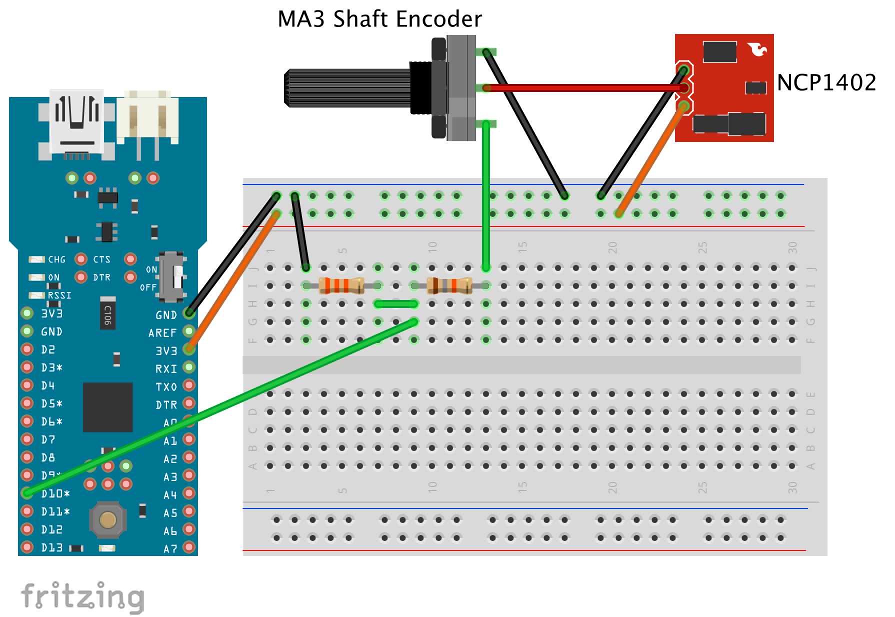
I built out the circuit on a breadboard and added it to my mess of wires, which included the accelerometer I had already connected to the Fio.

I created a simple program to display the values from the shaft encoder to a terminal on my computer. The most up to date code is available here.
/*
 * Simple program to collect data from an MA3 Shaft Encoder with PWM
 *
 * Values should be between 0 and 1023,
 * but sometimes mine returns greater than 1023
 */

int encoder_pin = 10; // digital pin 10
int encoder_value = 0;

void setup()
{
  pinMode(encoder_pin, INPUT);
  Serial.begin(57600); // baud rate of XBee
}

void loop()
{
  // read the time between HIGH values
  encoder_value = pulseIn(encoder_pin, HIGH);

  // send the data to XBee
  Serial.print("encoder value: ");
  Serial.print(encoder_value);
  Serial.write(10); //ascii line feed

  // wait 1 second, then loop again.
  delay(1000);
}
The values displayed on my terminal vary between 0 and ~1023. Sometimes I get values greater than 1023 and the values change when the encoder isn’t moving. I am not sure what is contributing to this variance, but in the future I will try to eliminate this noise with software by averaging the values over time and limiting the max to 1023.