The Arduino Fio is a 3.3V board, which means the inputs and outputs are 3.3V. The MA3 Shaft Encoder requires 5V input and outputs at 5V.
In order for the Fio to work with the Shaft Encoder, I need to convert voltages twice:
- Stepping up the 3.3V to 5V for the Shaft Encoder input
- Stepping down the Shaft Encoder output from 5V to 3.3V so it could be input into the Fio 3.3V input.
I didn’t know exactly how to do this, so I started simple and worked my way up.
Convert 5V output to 3.3V input
First, I wanted to convert 5V output to 3.3V input. This would be the part connecting the encoder output (5V) to the Fio input (3.3V).
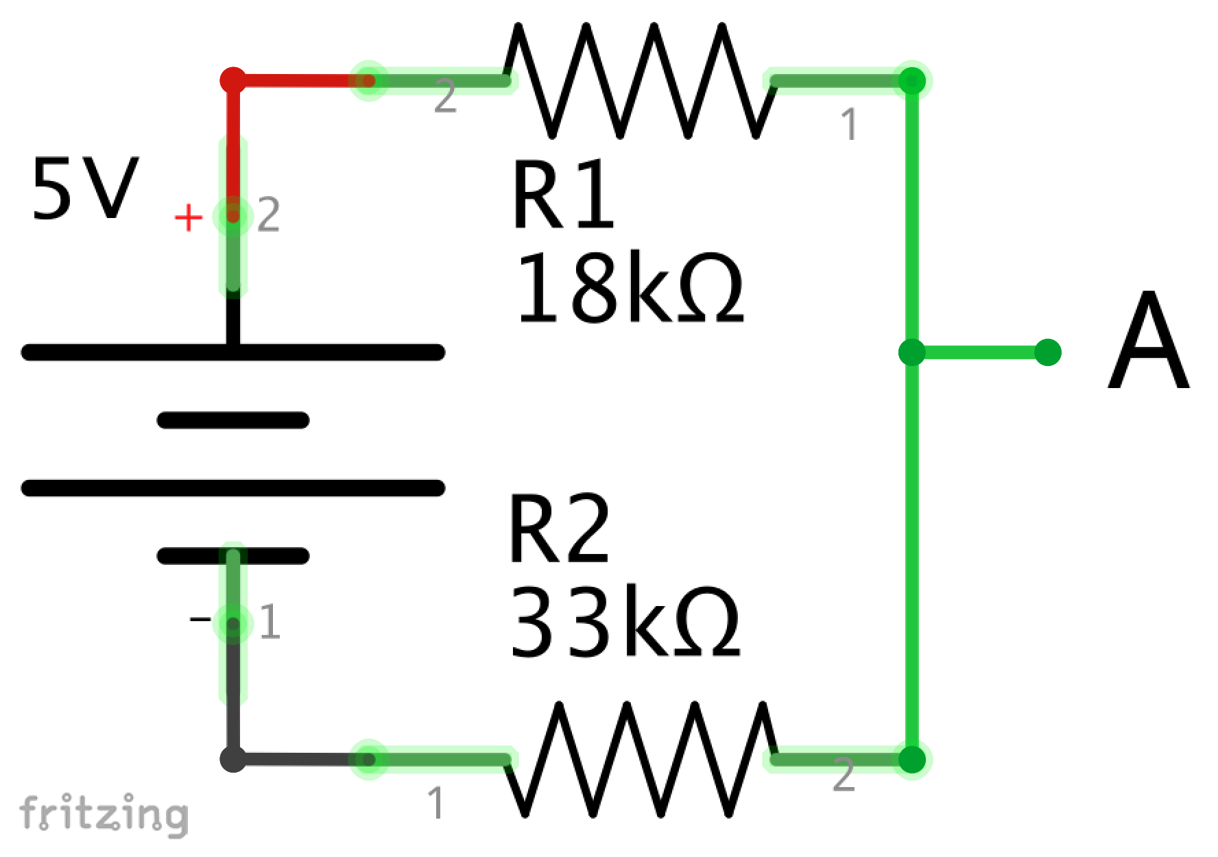
Through research, I determined that I would need to build a voltage divider, which uses the formula:Vout = Vin * (R2 / (R1 + R2))R1 is the resistance between the input and the output, and R2 is the resistance between the output and the ground. Since my desired Vout is 3.3 and my Vin is 5, I was looking for resistors where R1 was half the resistance of R2.
Since the ratio between the resistors is key, I could have used resistors with large or small resistance. In voltage dividers, the smaller the overall resistance the more accurate the output, the tradeoff is that more energy would be wasted. Since I am using battery power, but also care about accuracy, I wanted something in between. This post describes it pretty well.
Also, the formula assumes a perfect environment where the only resistance is through the resistors. In my circuit, the current drawn from the input pin would reduce the ratio between the resistors.
I am using PWM input, which is measuring the time between the peaks in voltage, so it isn’t super critical that I have exactly 3.3V. Based on this post I went with an 18k and 33k resistor, which should give me a peak of around 3.23V.
I built the circuit shown in Schematic 1.
Using my multimeter I measured
- 5V between the 5V input and ground
- 3.3V between A and ground
Supply 5V power to encoder, converting its output to 3.3V
My next step was to add the encoder to the circuit to make sure it could receive 5V of power, but have the output reduced to 3.3V.
Schematic 2 shows the circuit, though I am not sure that the image used for the encoder is appropriate.
I measured
- 5V between the 5V input and ground
- Max 3.15V between A and ground (depending on position of encoder)
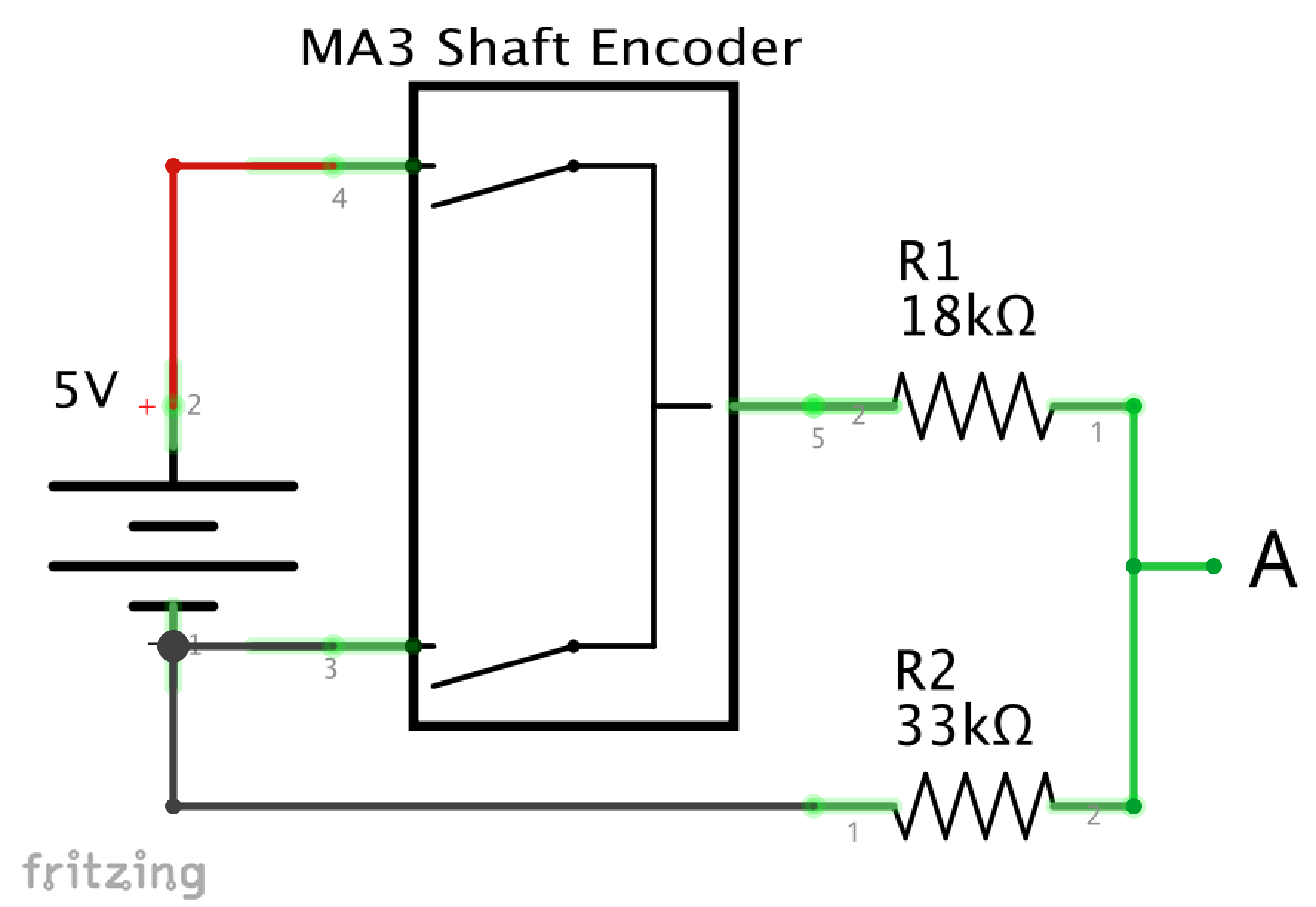
When I first measured at A, it was a lot less than 3.3V. I then turned the encoder and found that I could increase the voltage up to 3.15V. The encoder is using PWM and the voltage should be jumping between 0 and 3.15V with varying spaces between the highs and lows. My multimeter must average the voltage it is receiving, rather than show the peak.
I think the 3.15V is probably due to variations in individual resistors.
Convert 3.3V to 5V for Encoder input, and 5V to 3.3V for Encoder output
My final step before moving to the Fio was to use my 5V step up board to take a 3.3V input and output 5V to the encoder.
Schematic 3 shows the circuit I used. The part number on the step up should be NCP1402, not 1400.
I measured
- 5V between the input to the encoder and the ground.
- 5V between left side of R1 and ground.
- Max 3.15V between A and ground (depending on position of encoder)

Schematic 3: 3.3V input, stepped up to 5V for encoder, with output reduced to 3.3V at “A”.